
Blowdown Vessels – Blowdown Tanks – BG03 Compliant
Warning – IMPORTANT NOTICE:
BG03 introduced in 2018 means some existing installations AND Blowdown vessel ranges WILL NOT COMPLY.
 Some vent sizes MUST be BIGGER than before (see below excerpt from BG03)
Abbotts began making boilers in 1870, and continues to make blowdown vessels, blowdown tanks and equipment for the heating and steam industries.
Our Blowdown Vessels are: UKCA/CE Marked Built to ASME and BG03 (was HSE PM60) compliant SIZED – to your needs.
We have a standard range or can design and build blowdown tanks to your specification.
Sizing Blowdown Vessels
We are able to size the Blowdown vessel for you. Just let us know:
1) boiler working pressure
2) blowdown line size
3) proximity of blowdown vessel from boiler (less than or greater than 7m)
Please email us or ring 01636 704208 to discuss blowdown tank sizes and availability.
For details of our standard range click Blowdown Vessel Range.
We have a large range of ASME BG03 compliant Blowdown vessels for installations of all sizes – we also make specials to order. The size of vessel required can depend on many factors – some are explored here in our boiler blowdown sizing page
EXCERPT FROM Guideline BG03 for Vent sizing:
We also manufacture Flash vessels, Separators, Manifolds, and fabricated pipework – Please ring 01636 704208 or Email Us
Safety considerations in the design of Boiler Blowdown Installations – by the department of health – is very outdated and more of historic interest – but still includes some interesting facts and figures.
General information regarding blowdown vessels, blowdown tanks, and sources of additional information
(We have reproduced the following for your information only and cannot accept liability for the content – the original document should be viewed in full from the original source)
Extracts from HSE guidance note PM60 – Steam Boiler Blowdown Systems:
Introduction
This note gives guidance on steam boiler blowdown systems to those concerned with design, installation and operation of a steam plant. It is based on the recommendations of a committee consisting of representatives of the Health and Safety Executive, the Associated Offices Technical Committee, the Independent Engineering Insurers Committee…
It provides advice to ensure safe discharge of blowdown from boilers but does not contain guidance on all possible arrangements of boiler blowdown equipment which should only be installed after the design, construction and installations have been approved by a competent person.
Scope
This publication deals with the blowdown arrangements on boilers with a maximum evaporative capacity of about 8.8 kg/s (7000 lb/h) and a design pressure not exceeding 27.5 BAR G (400 PSIG). Large watertube boilers are excluded ie those with multiple blowdown circuits, but watertube boilers with one main blowdown line are included.
The blowdown tanks which have been considered here are steel pressure vessel of circular cross section. Design criteria for steel blowdown tanks of non-circular shape are not included and if these are used they must be designed and constructed as pressure vessels with similar design, construction and inspection criteria applied to them as for steel pressure vessels of circular cross section.
Advice given here only applies to the safe use of existing brick/concrete pits. Such pits are not normally recommended for new boiler installations as experience has shown that the general deterioration and state of repair is difficult to monitor. The effects of serious undetected leakage have been known to undermine foundations. If pits are necessary for new installations, they must be designed by a competent person and built under his supervision.
Reasons for Blowdown (Abbott blowdown receivers are built to pd5500 pressure vessel design code)
Steam Boilers are blown down at regular intervals to remove some of the suspended and dissolved solids which result from raising steam. These solids in the boiler water can give rise to foaming and overheating of the heat transfer surfaces of the boiler.
It is therefore necessary to control their concentration in the boiler by blowing down, which may be carried out intermittently (either manually or automatically) or continuously, or both. Intermittent blowdown is essential for boilers operating with internal feedwater treatment; it is the most effective method of removing sludge , particularly when applied in short sharp bursts.
Continuous Blowdown
Continuous blowdown is usually automatic in operation, and used when the quantity of blowdown to be discharged makes it necessary to supplement the intermittent blowdown through the main blowdown valve. The system is such that the correct amount of water is discharged from the boiler in order to keep the dissolved and suspended solids in the boiler water within predetermined limits.
When continuous blowdown is installed, it may be economic to recover the heat content of the discharge. When heat recovery equipment is installed, the pressure and temperature is reduced and the cool residual blowdown may then normally be discharged directly to drain rather than into the blowdown receiver.
Hazards
The sudden or rapid discharge of high temperature hot water is hazardous and because of the considerable amount of energy released, structures such as drainage ducts, culverts and sewers are likely to be damaged and unsecured manhole lids and slabs over blowdown pits are liable to be lifted. There is also a significant risk of injury to persons working in the vicinity of an inadequately protected discharge. Unsuitable blowdown tanks can fail catastophically under pressure and are potentially dangerous.
Legal Requirements:
The Health and Safety at Work etc Act 1974
Section 2 – requires employers to provide plant and systems of work which are, so far as is reasonably practicable, safe.
Section 6 – requires designers, manufacturers, importers, suppliers and installers to ensure that articles for use at work are safe when properly used. It also requires adequate information to be made available to the user.
The Factories Act 1961
Section 34 – prohibits entry into one of a range of boilers unless:
- all inlets through which steam or hot water might enter the boiler from any other part of the range are disconnected from that part; or
- all valves or taps controlling the entry of steam or hot water are closed and securely locked, and, where there id a common blowdown pipe or vessel, the blowdown valve on each boiler is so constructed that it can only be opened by a key which cannot be removed until the blowdown valve is closed and is the only key in use for that set of blowdown valves.
Public Health Act 1936
Section 27 (1)(b) – prohibits the passing into public sewers of waste steam or any liquid of a temperature higher than 110oF (43oC).
Design Considerations:
Tank
Boiler Blowdown Tanks should be constructed as pressure vessels to British Standard 5500 Unfired Fusion Welded Pressure Vessels, Category 3 or an equivalent national standard. (Note this is now PD5500 design code and a similar) A Boiler Blowdown Tank is not only designed to withstand internal pressure, but must possess sufficient structural strength to sustain the shock loading associated with intermittent blowdown, and be able to carry the weight of external attachments, and to withstand external pipe loadings etc.
For the pressures within the scope of this guidance note, past experience has indicated that it is good practice to design a blowdown tank on the basis of at least 25% of the maximum permissible working pressure of the boiler to which it is connected, subject to its possessing sufficient structural strength.
On a multi-boiler installation with boilers of varying working pressures, the highest maximum permissible working pressure should be used to determine the design criteria. The design temperature of the blowdown tank should be the temperature of saturated steam at a pressure equal to the design pressure. Adequate access must be provided to allow for cleaning and inspection.
The size of a blowdown tank depends on a number of factors such as:
- the boiler pressure;
- the size of the blowdown pipe system;
- the quantity of water blowndown at any time;
- the time between successive blowdowns;
- whether the blowdown enters the tank above or below the standing water level.
The water held within the tank performs two functions:
- It acts as a seal to prevent flash steam discharge through the water outlet to drain.
- It cools the incoming blowdown, so that the resulting water going to drain is at an acceptably low temperature. The degree of cooling depends on the water capacity in the tank and the quantity and frequency of blowdown. The water quantity in the tank should be at least twice that of the quantity of blowdown. Approximately half of the tank’s volume should be occupied by standing water and the remainder as airspace.
The testing of the low water cut-out and lock-out functions on an automatically controlled steam boiler consists of evaporating the boiler water down to the first low alarm level, after which the boiler is blown down to the second low water level, at which point an alarm sounds and the boiler goes to lockout.
If the amount of water blown out of the boiler between the first and second low water levels is greater than that discharged during routine blowing down of the boiler, the former quantity should be taken into account when calculating the size of the blowdown tank.
Pipework
Blowdown piping is subject to rapid pressurisation, high velocity flow, thermal shock and vibration, all of which can be severe. Pipework should be suitably supported, bends should be of large radius and its length should be kept as short as possible.
Piping should comply with British Standard 806 Specification for design and construction of ferrous piping installation for and in connection with land boilers.
Fittings should comply with British Standard 759 Part 1:1984 Specification for valves, mountings and fittings for application to boilers and to piping installations for and in connection with boilers or other appropriate national standards.
The vent and outlet pipe sizes largely determine the pressure rise within the blowdown tank and the vent pipe in particular must be generously sized. The vent should be designed to handle the flash steam released during blowdown and its size depends on:
- the boiler pressure;
- the size of the blowdown pipe system;
- the vent pipe layout and length;
- the manner in which the blowdown enters the tank ie above or below standing water level;
- any arrangements for condensing the flash steam;
- the maximum permissible rise in pressure within the blowdown tank (see ‘the vent pipe’.
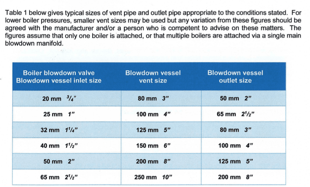
Table 1 gives the sizes of vent pipe and outlet pipe which are typical for the conditions stated. Any variation from theses figures should be by agreement with the manufacturer and/or approved by a competent person.
The Vessel Inlet
This must be at least equal in cross sectional area to that of the blowdown pipe or manifold. It can be either discharge into standing water or be located between the water level in the tank and the top of the tank. In the latter case, a deflection plate or baffles should be fitted in the tank to protect the shell against erosion.
The Vent Pipe
The venting arrangements of the blowdown tank should be designed so that the internal pressure does not exceed 0.35 BAR (5 PSIG) and should ensure that flash steam is vent safely and that there is no significant carryover of water at the exit of the vent pipe. The vent pipe must be taken from the highest point of the vessel and should not be less than the sizes given in Table 1. It should be as straight as possible with no valve or other obstruction to prevent free flow and ideally terminate in a suitable exhaust head with an adequate condensate drain. The vent should discharge into the atmosphere where it is not liable to cause personal injury or material damage.
The Water Outlet
The cross sectional area of the outlet should be at least 1.5 times the area of the inlet pipe. No valve or other obstruction should be fitted in the outlet pipe which should be connected to the tank so that the tank will remain approximately half full of water after each blowdown. The outlet connection may require a water seal incorporated in its design to prevent steam discharge. This may be achieved by extending the vertical leg of the water seal to within 150 mm (6 in) of the bottom tank. The top water seal should have a suitable opening to serve as a siphon breaker.
Table 1 Typical blowdown tank vent and outlet pipe sizes:
NOTE HSE Guidance Note BG03 now states Inlet size too – Watch Out
| Boiler Blowdown Valve Size | Blowdown Tank Vent Size | Blowdown Tank Outlet Size |
| 20 mm (0.75 in) | 80 mm (3.0 in) | 50 mm (2.0 in) |
| 25 mm (1.0 in) | 100 mm (4.0 in) | 65 mm (2.5 in) |
| 32 mm (1.25 in) | 125 mm (5.0 in) | 80 mm (3.0 in) |
| 40 mm (1.50 in) | 150 mm (6.0 in) | 100 mm (4.0 in) |
| 50 mm (2.0 in) | 200 mm (8.0 in) | 125 mm (5.0 in) |
| 65 mm (2.50 in) | 250 mm (10.0 in) | 200 mm (8.0 in) |
Notes
- The above figures have been produced assuming 18.3 m 960 ft) equivalent length of blowdown pipework, a vent height of 6.1 m (20 ft), a boiler pressure of 13.8 BAR G (200 PSI G) and a pressure build up within the tank not exceeding 0.35 BAR G (5 PSI G).
- Equivalent length. A pipework system consists of straight pipe and fittings such as bends, elbows, tees etc and valves, all of which cause resistance to flow. To find the total resistance through a pipework system it is usual to express the frictional resistance of fittings & valves as being the equivalent of the pressure drop through a number of linear metres of straight pipe. This length added to the length of the existing pipe is known as ‘equivalent length’.
Fittings
- Drainage – the vessels should be fitted with a suitable drain valve.
- Pressure Gauge – means should be provided for attaching a test pressure gauge.
- Water Level Gauge – this is not considered necessary but, if fitted, should be adequate for the design conditions.
Multi Boiler Installations
When used in conjunction with a multiple steam boiler installation, the blowdown tank should be sized to suit the boiler with the biggest blowdown rate. FOR SAFETY REASONS IT IS ESSENTIAL THAT ONLY ONE BOILER CAN BE BLOWN DOWN INTERMITTENTLY AT ANY TIME AND TO DO THIS WITH MANUALLY OPERATED INTERMITTENT BLOWDOWN VALVES, ONLY ONE BLOWDOWN VALVE KEY SHOULD BE AVAILABLE.
Manually operated intermittent blowdown valves should be so constructed that the valve key cannot be removed until the valve is fully closed. Where blowdown lines connect to an inlet manifold to the tank each of them must be fitted with a screw down non-return or alternatively a non-return valve and an isolating valve.
This is to prevent the possibility of steam and pressurised hot water being blown from a working boiler into another undergoing maintenance and in which men may be working. The manifold should be at least equal in cross sectional area to the largest boiler blowdown valve in the installation.
The blowdown lines from the boiler control chambers and water gauges should be piped into the main boiler blowdown line or manifold. The discharge should be led to a separate inlet on the blowdown tank.
In certain cases, such as multiple boiler installations where the total volume of blowdown from all the boilers exceeds the cooling capacity of the standing water in the tank, or continuous blowdown systems, it will be necessary to cool the water leaving the blowdown tank before it goes into the public drainage system.
This can be achieved simply by the use of an after cooler or by using multiple units ie, more than one blowdown line for the purpose of reducing the temperature and pressure of the discharge. The advice of a competent person should be sought when considering the use of blowdown tanks in series.
General Precautions
A water cooling device should be fitted to the tank if a blowdown tank is liable to contain hot water of such a temperature that blowdown causes the outlet temperature to exceed the permissible limit. As a result of blowdown the blowdown vessel can become very hot, so precautions should be taken to prevent accidental contact.
The precautions should guard against accidental contact, without interfering with the natural cooling contents of the tank, i.e. the use of guard rails may be preferable to insulating the tank.
Blowdown can be noisy and if this noise becomes a nuisance or a hazard measures should be taken to reduce it, which can be done at the design stage by keeping velocities lower than usual or by installing the tank elsewhere. Silencers may be fitted to the vents pipes, if necessary.
The tank and pipework should either be installed where the water will not freeze in cold weather, be protected so as to prevent freezing, or in cold weather be drained of all water, in which case THE TANK MUST BE FILLED TO ITS NORMAL LEVEL BEFORE BLOWING DOWN. The disposal of discharge should conform to any relevant Local Water Authority Regulations and, in any case the water temperature should not exceed 110oF (43oC).
Safe use of Brick/Concrete pits
Brick/concrete pits must be properly maintained. They should be drained, thoroughly cleaned out and examined by a competent person once in every 14 months, or at such intervals as recommended by a competent person. This person does not need to be the same competent person as the one who carries out the thorough examination of the boiler. Particular attention must be paid to the adequate venting of the pit so that it cannot be pressurised over 0.1 BAR G (1.5 PSI G).
Access to the pit should be properly safeguarded and the covers adequately secured unless they are properly fenced. Rubbish should not be swept into the pit. The vent pipe of the brick/concrete pit must be located at its highest point, and be protected against blockage.
It should discharge into the atmosphere where it is not liable to cause personal injury or material damage. Consideration should be given to changing over to a suitable steel blowdown tank where an existing pit is not of sufficient capacity or is not provided with an adequate vent pipe or requires major repairs.
Examination & Maintenance
Approximately every 14 months or at every thorough examination of the steam boilers, or at such intervals as are determined by a competent person, the blowdown tank should be positively isolated (i.e. double shut-off or blank flange) from the boiler(s), the tank drained, thoroughly cleaned out and examined. If the quality of the boiler feed is poor the blowdown tank may require draining and/or cleaning more often.
The positive isolation required by above paragraph is to ensure safety during examination of the blowdown tank. Where it is necessary for persons to enter a boiler in a multi-boiler installation, the fitting of a suitable blank flange in the blowdown line of the out-of-service boiler will provide the highest protection.
Where any anti-siphon hole is located in the top of the outlet pipe inside the tank, it should be kept clear of any blockage.
The Pressure Equipment Committee a s part of SAFed – The Safety Assessment Federation have produced a document on Guidance for the competent person when considering the suitability of blowdown receivers
associated with steam generating plant – SAFed Blowdown Receivers Installation Guidance 31st_August_2010 (1).pdf
The US Department of Energy – published a useful document on Boiler Blowdown energy Efficiency – advising on minimising boiler blowdown – see PDF attached here – Steam Blowdown efficiency
Blowdown Vessels or Blowdown Tanks can be built to a range of design codes: see also:
PD5500, EN286, DNV, ASME, LLOYDS, 97/23/EC, EN13445, 87/404/EEC, 2009/105/EC, ABS, BS5169
Leave a Reply
Want to join the discussion?Feel free to contribute!